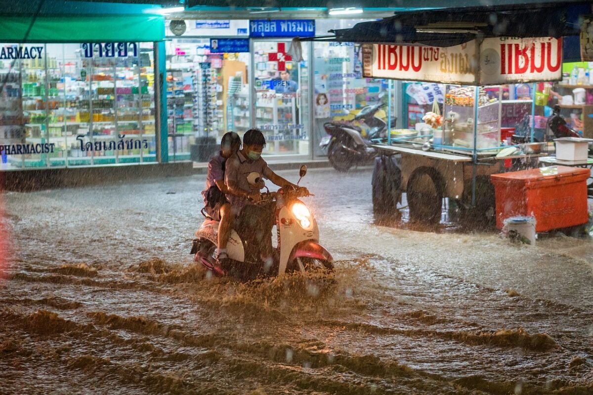
Drone-based EL mapping can be hugely helpful for assessing PV plant module damage and navigating insurance claims, especially after extreme weather such as the recent record rainfall in Dubai or golf ball sized hailstones in Texas.
As climate change accelerates, heat damage from wildfires can call for damage assessment, as can tracker or foundation failures after modules become twisted.
Detection of non-visible solar module defects has leapt forward with the advent of artificial intelligence-driven autonomous drone inspection.
EL, which involves applying an electrical current to PV cells to induce luminescence akin to that of an LED diode, is already used in PV manufacturing. The light emitted, captured by EL cameras, reveals solar cell health, with dimness highlighting a problem.
Solar cell cracks are commonly identified by EL testing. A classification system developed by Köntges et al distinguishes type A defects (microcracks with no disconnection), type B defects (cracks causing partial disconnection but allowing some power production), and Type C defects (cracks leading to complete disconnection). An EL image of a PV panel with all three crack types is pictured below. Type A and B cracks may not be detectable by conventional infrared sensors used in drone thermography.
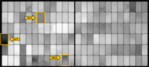
Image: Quantified Energy Labs
A study by Claudia et al, from German research center Forschungszentrum Jülich, found EL measurements uncovered extensive cell damage across almost all modules whereas drone thermography identified anomalies in around half. The authors of the paper, published in “Progress in Energy,” recommended EL and photoluminescence testing as well as drone thermography.
Solar project owners could consider the following workflow after severe weather, to assess damage, substantiate insurance claims, guide project rebuilds, and assess panel health afterwards.
Damage evaluation
If visual damage appears minimal, project owners may address issues through their operation and maintenance team.
In the event of a claim, the insurance company should be notified immediately. For evidence gathering, aerial photography can create a map illustrating displaced panels and modules showing obvious damage.
Initial evidence can be compiled by using AI to compare the aerial images with the plant’s layout design, to recognize damaged modules and qualify the damage. At large sites, fixed-wing unmanned aerial vehicles or manned aircraft, capable of flying at 500m, can be quicker than smaller-drone mapping.
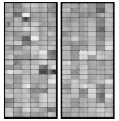
Image: QE-Labs
Rebuilding
EL inspection of a targeted sample of panels can reveal whether modules have sustained non-visible internal damage. A sample, which will help inform the scale of rebuild required, is assessed to save time on inspecting every panel.
Popular content
A strategic approach to sample EL inspection should be implemented, such as using the acceptable quality limit (AQL) table outlined in standardization guideline ISO 2859-1. This involves selecting a representative sample of modules from different areas across the PV site, acknowledging that damage severity may vary significantly between locations due to the heterogeneous nature of natural disaster impacts. A control sample in an undamaged portion of the plant, if one exists, should also be tested. Given the general subdivision of PV plants into distinct blocks, samples are generally chosen from each block to provide a well-rounded assessment of the entire installation.
For illustrative purposes, consider a 100 MW system comprising 150,000 modules, segmented into five blocks. Each block consists of 30,000 modules. With reference to ISO 2859-1, adopting a general inspection level I, the sample size code K dictates that 125 modules from each block are to be sent to a testing laboratory for measurement. Consequently, a total of 625 modules would be sent to the lab in this case.
Post-recovery
Phase three focuses on a thorough post-recovery evaluation and documentation of the new baseline condition of PV modules at a plant. This critical phase ensures that all recovery efforts are comprehensively assessed and accurately recorded, serving as a crucial step for operational resumption, finalizing the insurance claim process, and establishing a new baseline should there be another severe weather or heat event. In this third phase, a full EL inspection is carried out across all the affected blocks that have been rebuilt. This uncovers both any overlooked damage and new defects that may have been present in the new modules that resulted from the manufacturing process, shipping, storage, or installation. Significant energy production benefits may result from this detailed analysis.
In typical rebuilding scenarios where PV plants integrate new modules to replace the broken units, there will be a mix of new and existing modules in the solar project. This integration, although it may be the quickest and most cost-effective method, introduces mismatches in the PV plant that could affect overall project efficiency and should be monitored carefully. High-sensitivity EL inspection also serves as a good tool to document the final position of old and new modules in a PV plant by documenting the difference in luminescence signal: new modules exhibit brighter luminescence, signaling higher efficiency and minimal degradation, in contrast to the older modules' dimmer output, which is indicative of wear and reduced performance.
It should also be noted that, upon identifying module defects through a comprehensive EL inspection, insurance companies may request verification of the defects' origins to determine if they resulted from the natural disaster, or pre-dated the event. The figure below shows EL images from a PV plant after a severe hailstorm, depicting modules with cell cracks. The modules with dendritic cracks and dark areas are a clear indicator of hail impact damage. However, without a baseline established before the hailstorm, the module shown on the right with minor cracks may fail to meet claim criteria due to the inability to conclusively determine the origin of the cracks, despite the potential long-term reliability issues the cracks pose due to potential future crack propagation. This illustrates the need for periodic EL scans of a PV plant to have an accurate baseline condition of solar modules prior to a storm event or other PV plant failure.
 About the author: Yong Sheng Khoo (Ph.D.) has been actively engaged in solar research since 2010, publishing impactful work that ranges from understanding PV degradation to optimizing real-world performance. With his extensive engineering and solar knowledge, he co-founded QE-Labs to provide autonomous drone and digital solutions to the PV industry.
More details about QE-Labs' EL testing are available here.
The views and opinions expressed in this article are the author’s own, and do not necessarily reflect those held by pv magazine.
This content is protected by copyright and may not be reused. If you want to cooperate with us and would like to reuse some of our content, please contact: editors@pv-magazine.com.

By submitting this form you agree to pv magazine using your data for the purposes of publishing your comment.
Your personal data will only be disclosed or otherwise transmitted to third parties for the purposes of spam filtering or if this is necessary for technical maintenance of the website. Any other transfer to third parties will not take place unless this is justified on the basis of applicable data protection regulations or if pv magazine is legally obliged to do so.
You may revoke this consent at any time with effect for the future, in which case your personal data will be deleted immediately. Otherwise, your data will be deleted if pv magazine has processed your request or the purpose of data storage is fulfilled.
Further information on data privacy can be found in our Data Protection Policy.