A group of scientists led by Norway’s Institute for Energy Technology (IFE) has developed a novel model for wave-induced loss (WIL) of floating photovoltaics (FPV).
The model consists of three main steps, namely wave-structure-interaction, irradiance and electrical modeling.
“For FPV systems, waves will, if present, induce movements in the floating structures that the PV panels are mounted on. First, the movement will tilt the panels away from the set panel orientation. Second, if the panels are mounted in such a way that they can move independently, different irradiance conditions on each of the panels within the string cause a mismatch loss,” said the researchers. “In this paper, we propose a method for modeling the total loss from these two components combined and refer to this as the WIL.”
To create the model, the team used the in-house software 3DFloat to simulate the movement of the PV panels and Python libraries for irradiance and electrical modeling. The first step, the one of wave-structure-interaction, analyses how the FPV moves due to the waves. It uses a standard ocean wave model, assuming that the PV panels follow the local wave motions exactly without moving horizontally.
The second part, which models irradiance, uses the tilt angle of the panel that is yielded from the previous stage. Based on that, the third step of electrical modeling uses the PVMismatch simulation library to calculate the electrical output.
WIL is then calculated as the percentage difference between that result and the simulated result of a static setup.
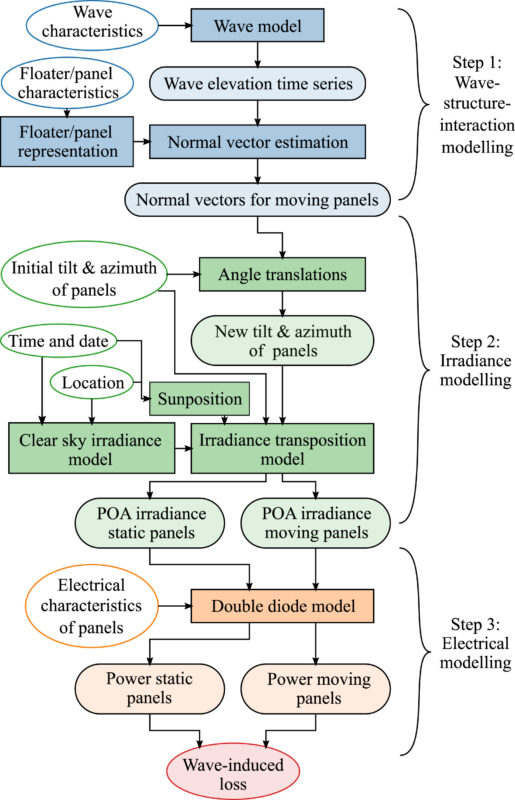
Image: Institute for Energy Technology (IFE), Solar Energy, CC BY 4.0
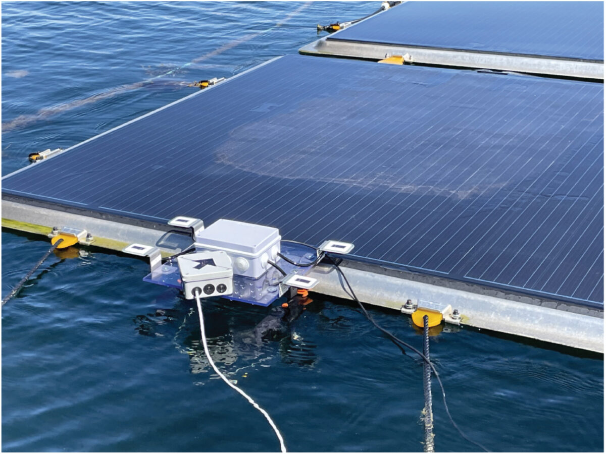
Step 2 of irradiance modeling was tested and verified against an experimental model. This experiment was performed on an FPV prototype provided by the company Sunlit Sea, and situated in the Oslo fjord. It consisted of two strings with four PV panels each. Four irradiance sensors, one accelerometer and a 3D gyroscope were attached to the edge of one of the PV panels for data gathering.
The analysis showed that the modeled irradiance matches the measured irradiance “well” and offers an acceptable agreement with the measurements, with root mean square error (RMSE) between the modeled and measured irradiance being 2.8 W/m2. “However, the modeling has a tendency to slightly underestimate the extreme values of the measured irradiance,” the scientists stressed.
Following the successful validation, the group demonstrated the model with a few scenarios. Among the changing parameters tested were the (0◦N, 0◦E) and (50◦N, 0◦E) locations, with waves of 0.25 m, 0.5 m, 1 m, and 3 m. Waves with a direction of 0°, traveling along the length of the string; 90°, traveling across the width of the PV string; and 45°, approaching the PV string at a diagonal angle, were tested.
“Higher WIL was found for systems further from optimal orientation and under conditions with steeper and higher waves. The WIL also increased with increasing PV string length and when the wave direction changed from orthogonal with the length of the string to parallel to the string,” the results showed. “As an example, the WIL ranged from 3.3% for a significant wave height of 0.25 m to 6.7% for a significant wave height of 1 m. This indicates that the WIL can be significant and should be considered for energy yield analysis.”
The novel technique was introduced in “Modelling wave-induced losses for floating photovoltaics: Impact of design parameters and environmental conditions,” published in Solar Energy. Researchers from Norway’s IFE, the University of Oslo (UiO), and India’s Himachal Pradesh University have participated in the study.
This content is protected by copyright and may not be reused. If you want to cooperate with us and would like to reuse some of our content, please contact: editors@pv-magazine.com.

By submitting this form you agree to pv magazine using your data for the purposes of publishing your comment.
Your personal data will only be disclosed or otherwise transmitted to third parties for the purposes of spam filtering or if this is necessary for technical maintenance of the website. Any other transfer to third parties will not take place unless this is justified on the basis of applicable data protection regulations or if pv magazine is legally obliged to do so.
You may revoke this consent at any time with effect for the future, in which case your personal data will be deleted immediately. Otherwise, your data will be deleted if pv magazine has processed your request or the purpose of data storage is fulfilled.
Further information on data privacy can be found in our Data Protection Policy.